john.squibb
Professional Programmer, Musician, Maker
Eurorack Power Breakout Board
When designing Eurorack synthesizer modules, I frequently hook prototypes on breadboards up to my rig for testing work-in-progress designs with my other modules. At first, I simply stuck some jumper wires in the end of an IDC cable and ran them to the bus bars on my breadboard, but after getting the wires crossed and starting a small fire, I decided I needed something a bit safer.
Designing a Solution
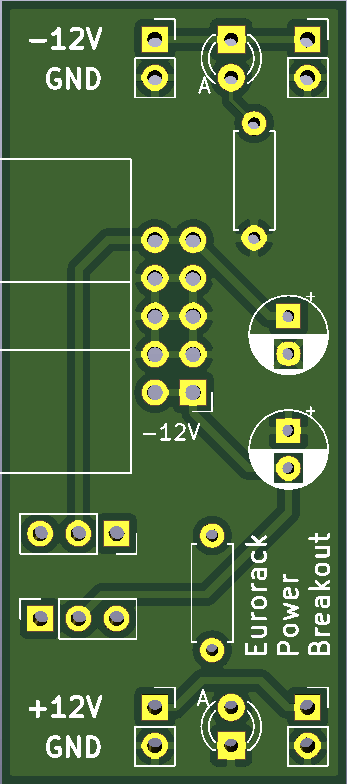
Using KiCad, I designed a breakout board to fit across the span of a standard breadboard. I uploaded the Gerber files to my favorite PCB fabrication service, JLCPCB, and within a few days the first run of prototype boards arrived. I ordered a few dozen of these panelized for around $25 USD with 2-day DHL shipping.
Usage
The breakout board is designed to be placed on the left-hand or right-hand side of a standard breadboard with 0.1" lead spacing. For the left-hand orientation, the -12V connection will be on the top power bus rail, and +12V on the bottom. This coincides with the power pins of a left-hand orientation of a TL074 op amp IC package that I frequently use (pins 4 and 11). The image below shows an assembled breakout board in a left-hand orientation. The board is labelled, but I also use different color LEDs for +/- so that I can determine the orientation at a glance.
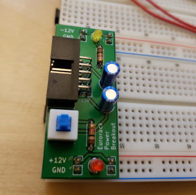
I've done two runs of these boards to sort out the exact designs show here, and have recently opted to use a lower profile capacitor in order to reduce the likelihood of bending the leads when handling the breakout board. I've assembled about ten of these for use on breadboards as I prototype, and am quite happy with the form factor.
Open Source
If you would like to build some of these, check out the EurorackPowerBreakout GitHub Project, where I've uploaded and open-sourced the designs and details. The Gerber files are also included for upload to a PCB Fabrication service. Check out the Interactive Bill of Materials for a full listing of parts (also included in GitHub repository).
Next Steps
For now, these work great with cables sticking out of my Eurorack cabinet, or in combination with a bus board I put together for another project. Ultimately, I plan to put together a Eurorack interface panel that I can properly mount in my rig. I'm not quite sure what that will look like just yet, but I'll update the article here when I arrive at a design!
© 2021 john.squibb | statically generated | Privacy Policy | Cookie Policy